IN DEPTH ANALYSIS OF ENERGY-SAVING AND CURRENT EFFICIENCY IMPROVEMENT OF
ALUMINUM REDUCTION CELLS
Yan Feiya1, Marc Dupuis2, Zhou Jianfei1, Ruan Shaoyong1
1CHALIECO GAMI Guiyang Guizhou China 550081
2GéniSim Inc., 3111 Alger St., Jonquière, QC, Canada, G7S 2M9
Keywords: aluminum reduction pot, prebaked pot, pot voltage, energy consumption.
Abstract
In view of the existing aluminum overcapacity and lower
aluminum price in China, many companies took measures to
reduce the production cost and the energy consumption, but there
has been no normalized theory and method defined as yet.
To address these issues, this paper puts forward the evident effects
of energy-saving and current efficiency improvement in
aluminum reduction cells using new thermal insulation pot lining
design, application of optimal cathode structure and reduction of
horizontal current device. A proper application of new lining
materials and combination of relevant process parameters based
on the finite element software ANSYS® and thermal field
simulation software as the calculation method combining the
actual production data are also used. Practice proves that the
above-mentioned method combining design, simulation and
experiment can become the effective and feasible way to achieve
low energy consumption, low cost and high profit.
Introduction
In recent years, the nonferrous metal industry sets off an upsurge
of scientific and technological innovation activities on quality and
capacity increase, energy-saving, consumption-reduction and
environment protection. The key technologies in aluminum
reduction area such as low temperature operation, intensifying
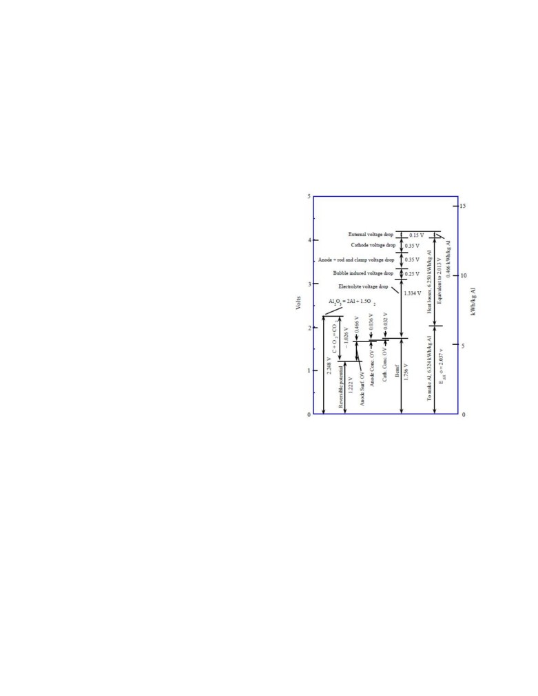
Figure 1. Energy balance relationship
[1]
current, on-line measurement of superheat, “3-variables” control
technology, anode slotting technology, irregular cathode
Figure 1 shows that the heat input/output may be divided into the
technology, improved thermal insulation lining design, cathode
above items based on pot energy balance principle. The object of
design that reduces metal pad horizontal current, application of
voltage reduction is the voltage combination in the heat input, the
new lining materials, inert anode etc. have been studied and are in
majority of which is voltage drop between anode-cathode.
the process of being implemented.
It should be pointed out that the high-temperature production
This will soon raises Chinese aluminum reduction technology to
during aluminum reduction mainly depends on the Joule heat
the world advanced level. Moreover, the consumption of energy
generated in the bath in which the current passes from the anode
and raw material for aluminum reduction production has been
to the cathode. The normal production shall be kept through the
very high in recent years, especially power consumption. With the
dynamic balance of heat output and heat input during operation. If
energy crisis, the aluminum reduction production cost must be
the Joule heat generated from heat input is not enough to maintain
reduced without delay. For this, the most efficient method is to
the heat output, the pot shall get cool gradually, and the process
reduce the DC consumption by increasing current efficiency (CE)
system shall be damaged.
and reducing pot voltage.
Therefore, the energy balance of the pot is maintained by reducing
Analysis of mechanism and nature of pot work voltage
the heat dissipation in heat output combination as well as the
reduction based on energy balance principle
voltage in heat input combination so as to reduce the voltage.
The pot energy balance was summarized by Warren Haupin as
shown in Figure 1.
1
Analysis of potentialities and approaches on voltage
Where:
reduction by voltage composition of heat input
ia
is the Anodic Current Density (A/cm2);
χ
is the Electrical Conductivity of the Bath (1/Ωcm);
δ
is the Bubble Layer Thickness (cm);
ta
is the Adhering Bubble Thickness (cm);
ε
is the Gas Fraction in the Bath (0.02 · %Al2O3);
fc
is the Fraction of the Anode Covered with Gas ().
From Equations 2 and 3, we can see that the mechanism of bubble
voltage drop reduction lies on improving the bubble release
capacity, hence reducing the bubble coverage fraction and
reducing the bubble thickness.
Until now, the measures taken by the industry mainly include the
slotting of anodes, the control the length-width ratio of anode, the
Figure
2. Heat input structure and approaches of
improvement of bath composition, etc.
voltage reduction
The slotted anode can make the bubble release from the anode
The total pot voltage is just the sum of the parts as follows[2,3]:
bottom more efficient to reduce the bubble coverage fraction and
the bubble thickness, so as to reduce the bubble voltage drop of
Vpot = Vanode + |Ee| + ηsa + ηca
anode, thus reducing the pot voltage.
+ Vbub + VACD + ηcc + Vcath + Vext
(1)
There is deeper research on the slotted anode technology abroad,
Where:
including slotting location, slotting width, slotting depth, slotting
process, etc. At present, the more mature slotted anode structure
in China consists of 2 slots (at trisection location), slot width
Vpot
is the Pot Voltage (V);
around 1~1.5 cm, slot depth or height of half of anode consumed
Vanode is the Anode Voltage (V);
in anode change cycle as per the anode height generally. The
|Ee|
is the Equilibrium Potential (V);
slotting process is generally vibrating forming plus slot cleaning.
As per a lot of on site tests in China, using slotted anode can
ηsa
is the Anode Surface Overvoltage (V);
reduce the pot voltage by 30~60 mV.
ηca
is the Anode Concentration Overvoltage (V);
Vbub
is the Bubble Voltage (V);
Bath voltage drop[3]
VACD is the Voltage Across the ACD (V);
ηcc
is the Cathode Concentration Overvoltage (V);
Vcath is the Cathode Voltage (V);
Vext
is the External Voltage (V).
Where:
Figure 2 shows that if the design dimensions of the pot are
determined, the object of pot voltage reduction is mainly the
ACD is the Anode to Cathode Distance (cm).
voltage drop reduction between the anode and the cathode
(industry term: active voltage). If the CE is fixed, the object of
Equation 4 shows that the mechanism of ACD voltage drop
voltage reduction is mainly the voltage drop of bubble (Vbub) and
reduction lies on changing the bath composition and reducing the
ACD itself.
in the bath across the ACD (VACD).
Perspective of changing the bath composition
Bubble voltage drop[3]
Up to now, the measures taken in industry are as follows: the bath
conductivity is increased by adding the additive, in which the
most effective method is to add the LiF, and there will be
significant effect combining with low bath ratio technology.
From the present calculation and statistical data, it is seen that for
every increase of LiF by 1%, the voltage drop of unit ACD (cm)
will be reduced by about 3~5 mV. For a pot with an ACD of 5 cm
for example, every 1% LiF addition can reduce the voltage by
15~25 mV, and every 3% LiF addition can reduce it by 45~75
mV, which is a considerable effect.
2
The main designs tried in the aluminium industry in China have
Perspective of ACD reduction
been a stepped surface cathode, a sloped surface cathode and a
flow resistance block.
The ACD reduction is theoretically divided into: (1) effective
ACD reduction; (2) non effective ACD reduction (see Figure 3).
Stepped surface cathode metal flow model
Figure 4. Stepped surface cathode design
Figure 3. 3-layers structure model of ACD[4]
As shown in Figure 3, the ACD consists of 3 parts including a- a
bubble layer, b- an effective ACD layer and c- a non effective
ACD layer. Zone a depends on the width of the anode, the specific
gravity and viscosity of liquid bath, the surface tension of bath to
carbon dioxide gas, the alumina concentration, etc.; zone b is a
heating area for maintaining the high temperature production of
the pot, as well as an isolation layer for making the wave crest of
metal away from the lower edge of bubble to avoid the back
reaction; zone c depends on the MHD cell stability.
For the conventional pot, if the ACD is
5 cm, as per the
calculation and averaged measurement, generally zone a (bubble
Figure 5. Model of metal flow velocity of stepped
layer) is about 0.5cm, zone c (non effective ACD) is 1.5~4 cm (it
surface cathode
has relationship with the pot stability), hence, zone b (effective
ACD) is 0.5~3 cm. The irregular cathode technology and the
Sloped surface cathode metal flow model
horizontal current reduction technology are decreasing the height
of zone c (non effective ACD) to reduce the pot voltage; and the
current intensification technology is decreasing the height of zone
b (effective ACD) to reduce the pot voltage, i.e. the lowest voltage
of current intensification selected in order to satisfy the heat
balance, thus obtaining the lowest height of zone b assuming no
CE loss. Therefore, if the pot with bad stability has current
intensification to reduce the voltage, it is highly possible that it
will reduce the height of zone c and bring about more back
Figure 6. Sloped surface cathode design
reaction, thus the pot will experience CE loss and overheating.
We can divide the type of applications used to reduce the ACD in
three categories: (1) irregular cathode technology; (2) horizontal
current reduction technology; (3) current intensification.
Irregular cathode technology
In 1994, Vittorio de Nora put forward the thinking of the irregular
cathode structure. The irregular cathode structure is adopted to
change the metal and bath flow state and reduce the melt flow
velocity and the interface wave range of metal surface (reduce the
non effective ACD), thus improving the pot stability in order to
gain the option to reduce the ACD. Such technology is a kind of
method to reduce the non effective ACD.
Figure 7. Model of metal flow velocity of sloped surface
cathode
3
Comparison of results obtained
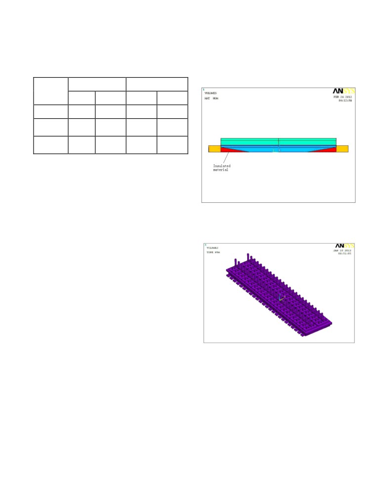
Special insulation[5] between cathode carbon block and collector
bar
Table
1 is the comparison of calculation and measurement
between irregular cathode and standard cathode in a plant in
This new kind of design is a cathode assembly which reduces the
China.
horizontal current by adding an electrically insulated region
between the cathode carbon block and the collector bar, as shown
Max. flow velocity
Max deformation of
in Figure 8.
(cm/s)
metal surface (cm)
Calcula-
Measure-
Calcula-
Measure-
tion
ment
tion
ment
Standard
15.73
14.99
1.82
1.97
pot
Irregular
7.47
8.24
0.65
0.51
cathode
Variation
52.50%
45%
64.30%
74.10%
percentage
Table 1. Comparison of calculation and measurement
between irregular cathode and standard
cathode in a plant
Compared to the standard cathode, for the irregular cathode the
flow velocity is reduced by about 50%, the maximum deformation
of metal surface by 65~75% and noise by 10~15%. At present,
the voltage of the most of irregular cathode pots in China is about
Figure 8. Cathode assembly for restraining the
3.7~3.9 V, based on the calculation of 2~3% of CE loss. The
horizontal current ( JY)
power consumption can be reduced by 560 kWh/T Al compared
to the standard cathode pots.
This design has been modeled using a 3D generic parametric
whole pot model, based on ANSYS® 13.0, as shown in Figure 9.
Horizontal current reduction technology
It has been proved by the long-term practice that the fluctuation of
metal liquid layer and bath liquid layer has close relationship with
the horizontal current and the vertical magnetic field, which
combined brings about the pot voltage fluctuation. So for a given
vertical magnetic field, a reduction of the horizontal current in the
metal can make possible a significant reduction of the height in
the metal pad, reducing the cell heat loss and so provide an
opportunity for pot voltage reduction, while maintaining the pot
production and increasing the CE, all for the purpose of reducing
the specific energy consumption.
The horizontal current has relationship with the following factors:
1) Geometric dimensions, such as width and length of cathode,
Figure 9. Geometry of the ANSYS® based 3D generic
width and height of collector bars;
parametric whole pot model
2) Material of cathode, such as material of cathode carbon
block, connection method between the cathode carbon block
The comparisons of simulation results between the cathode
and the collector bar;
assembly without restraining horizontal current and that with
3) Geometric dimensions of the pot, such as dimension of
restraining horizontal current are shown in Figures 10 and 11
thermally insulating pier, hence the position of the ledge toe;
respectively.
4) The location of the collector bars exit out of the pot (side
wall or otherwise).
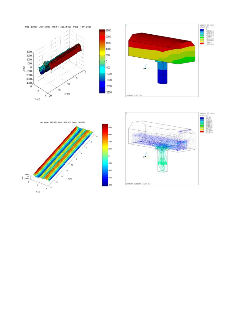
From the above analysis and comparisons it shows that the
cathode assembly with insulation has a good effect on the
The up to date prototype tests were designed to:
reduction of the horizontal current; from the curve distribution, it
shows that the curve of no sloping pasting presents the raised
1) Increase the electrical insulation between cathode carbon
parabola
(Figure
10) with a maximum value of 0.26 A/cm2.
block and collector bar;
However, the curve of the anode bottom middle of sloping pasting
2) Try a cathode design with bottom exit collector bar.
presents a leveled curve (Figure 11) at a value of 0-0.04 A/cm2.
4
Figure 12. Voltage results for the cathode with bottom
exit collector bar
Figure 10. Cathode assembly without restraining
horizontal current (JY)
Figure 13. Current density results for the cathode with
bottom exit collector bar
Figure 11. Cathode assembly with restraining
horizontal current (JY)
Current intensification
From the curve distribution and values it shows that the sloping
This technology reduces the voltage and maintains the relative
pasting technology has obvious effect for restraining the JY. At
constant heat input by the current intensification, thus obtaining a
the moment in China, the different insulated materials for this
way to maintain the stable thermal balance. Such way is a method
technology are adopted for test and engineering applications.
to reduce the effective ACD, the premise of which is that the pot
has good MHD stability.
Cathode design with bottom exit collector bar
The development trend of current intensification for advanced cell
This kind of design is the cathode assembly which reduces the
technology outside of China at present is as follows:
horizontal current by changing the collector bar design and cell
exit location. Figures 12 and 13 show that the cathode voltage
1) Rio Tinto Alcan (Pechiney): pot capacity: 300 kA → 400
drop is 194 mV (anode current density is 0.73 A/cm2) which is a
kA, anode current density: >0.98 A/cm2 , pot voltage: <4.02
reduction of 70~100 mV compared to that of traditional cathode
V, CE: 95%-96%, DC consumption: 12800 kWh/T Al;
based on the same anode current density. From the horizontal
current reduction analysis, it shows that the vertical current
2) Hydro Aluminium: pot capacity: 300 kA → 420 kA, anode
density in the cathode carbon block increases by about 0.2 A/cm2
current density: > 0.99 A/cm2, pot voltage: 4.08 V, CE: 94%-
due to bottom exit. This technology is currently only in test phase,
95%, DC consumption: 12800kWh/T Al;
and the potential of voltage reduction needs to be proven.
5
3) Dubal: DX type pot capacity: 340 kA → 370 kA, anode
current density: >0.99 A/cm2, pot voltage: 4.15 V, CE: 95%-
96%, DC consumption: < 13000 kWh/T Al.
Today, the development condition of advance representative pot
type in China is: an anode current density of current
intensification for pots operating from 200 kA to 400 kA already
that reaches 0.8~0.83 A/cm2, and a voltage of 3.85~4.05 V.
Conclusions
In summary, through lots of prototype tests, mathematical
modeling and comparison, the main effective approaches for
reducing the pot voltage are as follows at present in China:
· Change of bath composition
· Sloped surface cathode
· Cathode assembly technology for restraining JY
· Current intensification
· Optimization of anode design
· Cast iron rodding for cathode
For the pot with the above technologies, for example in a plant in
China the voltage is 3.75~3.85 V and the CE is above 94% [6][7].
Compared to the traditional pot with voltage being 4.1~4.2 V and
CE being 93%, the energy consumption can be reduced to about
1250 kWh/T Al, and reduced by about 62.5*107 kWh per year
based on an annual production capacity of 500 thousand tons.
The operation cost savings are about 312 million Yuan per year
based on power price being at 0.5 Yuan per kWh.
References
[1]
Warren Haupin, Halvor Kvande,
“Thermodynamics of
Electrochemical Reduction of Alumina”, TMS Light Metals,
2000, 379-384.
[2]
Jay Bruggeman, “Pot Heat Balance Fundamentals”, Proc 6th
Aust Al Smelting Workshop 1998, 167-189.
[3]
Grjotheim, K., Kvande, H.
(eds.), Introduction to
Aluminium Electrolysis, Aluminium-Verlag, Dusseldorf,
1993, 144-145.
[4]
Tian Yingpu, Wang Hang, “Pot anode cathode distance
composing model and process energy consumption”, Light
Metals, 2011, 567-568.
[5]
Zhou Jianfei, “A kind of cathode assembly to improve the
pot stability, increase CE, reduce the energy consumption
and prolong the pot life”, Chinese Patent: 201020504034.
[6]
Chen Cairong, “Production index of 80KA and 300KA pot
in Yunnan Aluminum Plant”
(internal data), Guiyang
Aluminum Magnesium Design & Research institute
Corp.Ltd (GAMI), 2011.
[7]
Zhou Jianfei, “Thermal field test report of 80KA pot in
Yunnan Aluminum Plant”
(internal data), Guiyang
Aluminum Magnesium Design & Research Institute
Corp.Ltd (GAMI), 2011.
6